01 Start with the object
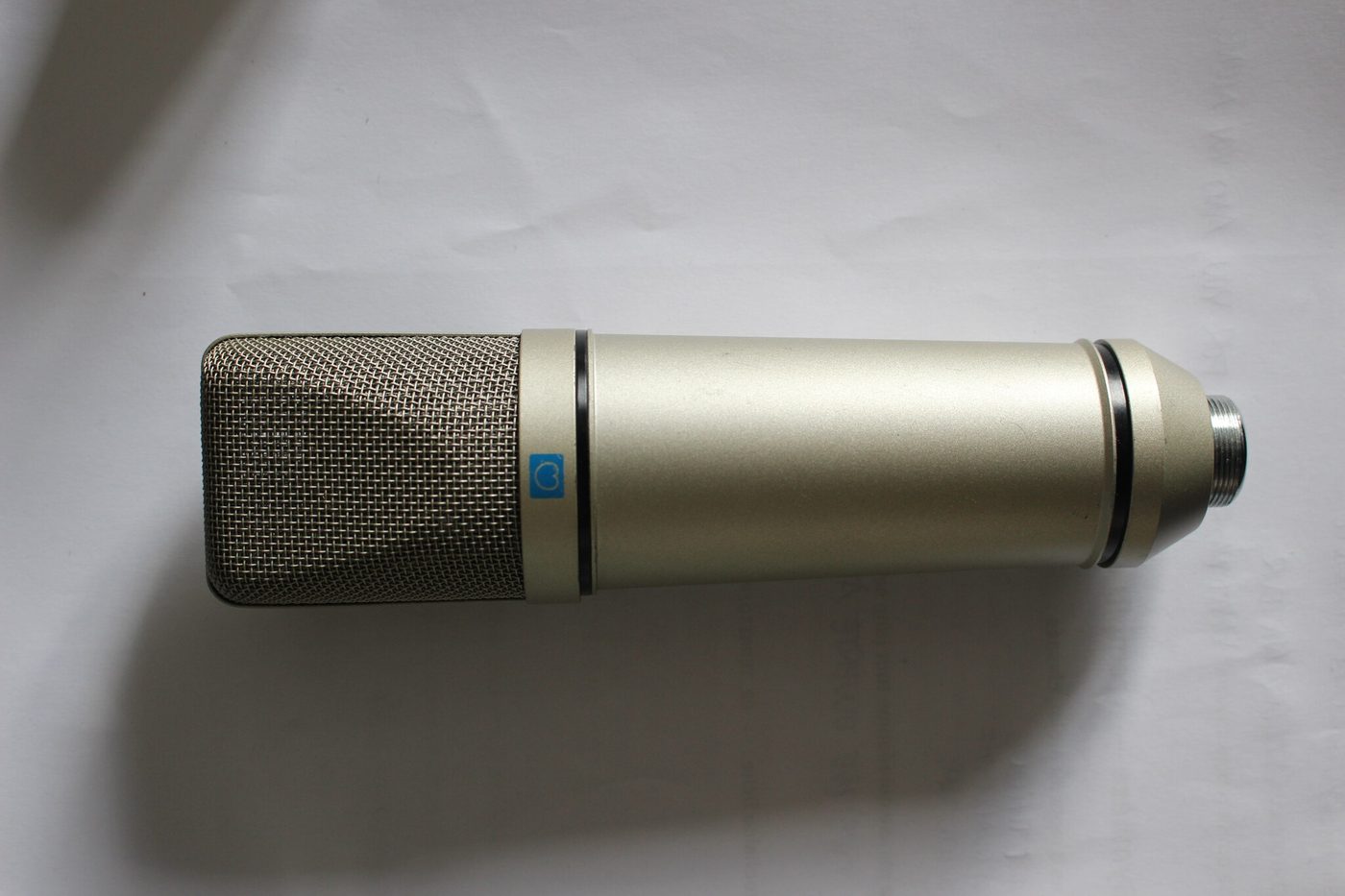
This is a studio microphone — the kind you'd see in front of a singer in a vocal booth, not the one on a gaming headset.
What makes this one different is that nobody bought it: it was built. The plans, the parts and the tests are all public, so anyone can do it again.
- Parts, if you build one
- about €78, plus an adapter cable
- A shop-bought equivalent
- a few hundred euros
- Build time
- 4 to 6 hours
- Status
- one working prototype (P1)
02 What's inside
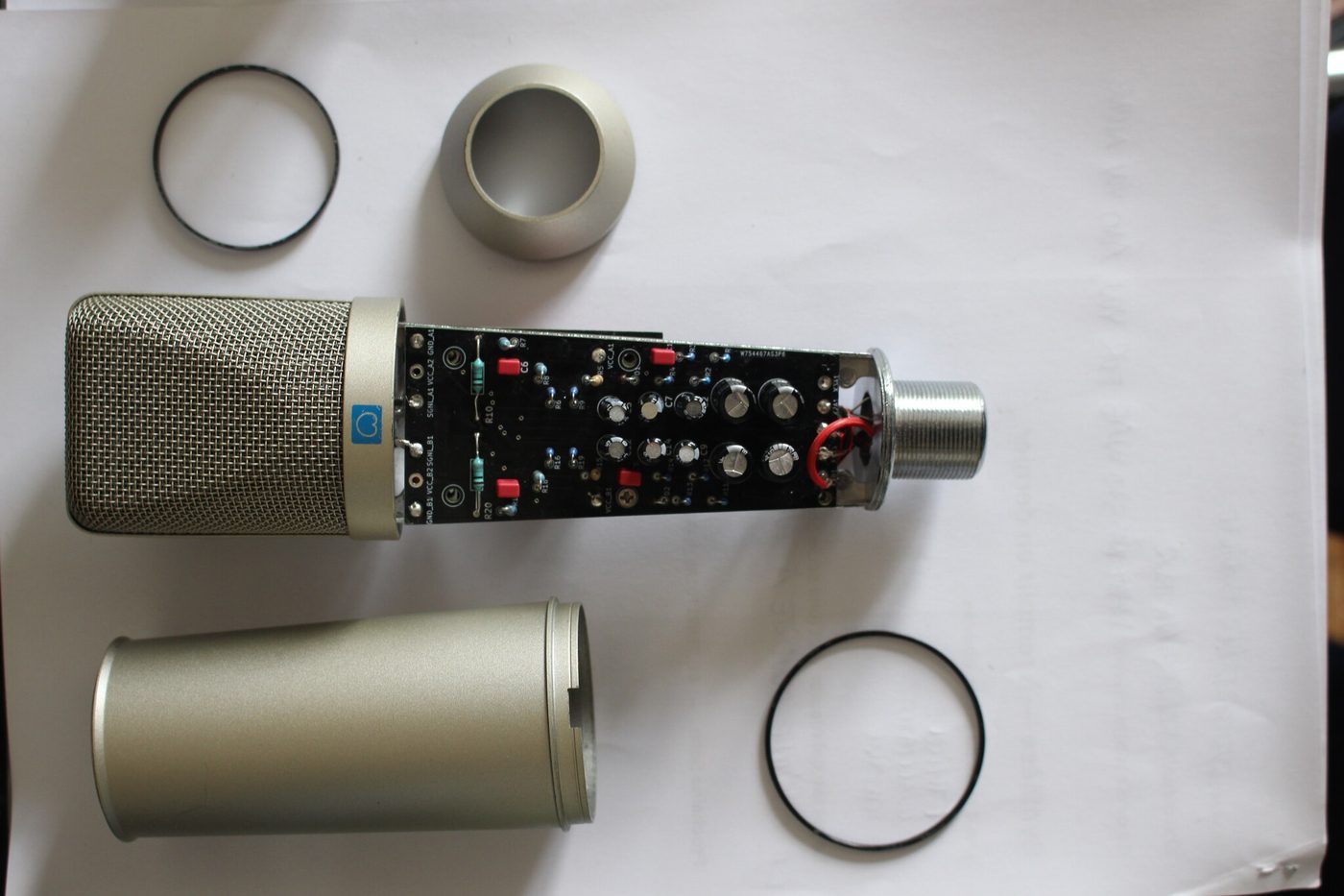
A studio mic comes down to four things:
- the grille, on the left — it protects the capsule and breaks up gusts of air;
- the metal tube, at the bottom — the body;
- the rings and seals — the hardware that holds it all together;
- the long black board — the electronics, which slide inside the tube.
The tube isn't just a shell. While the electronics sat out in the open, a 50 Hz hum — the hum of household mains power — got into every recording. It vanished the day everything went inside the metal. The body works as a Faraday cage: it shields the inside from the electrical fields you find in any room.
03 The part that hears


At the top of the mic sits the capsule. Inside is an extremely thin membrane, stretched like a drum skin and coated in gold.
- You speak, and your voice makes the air vibrate.
- The air makes the membrane vibrate, by a few millionths of a millimetre.
- That tiny movement becomes an electrical signal.
For that last step to work, the membrane has to stay electrically charged the whole time — a bit like having a small battery built in. One of the two boards below takes care of that.
The catch is that the signal coming out is tiny and very fragile. Plug it straight into a speaker and you'd hear nothing. It's so weak that the slightest interference drowns it out — which is what everything else is for.
04 The two circuit boards

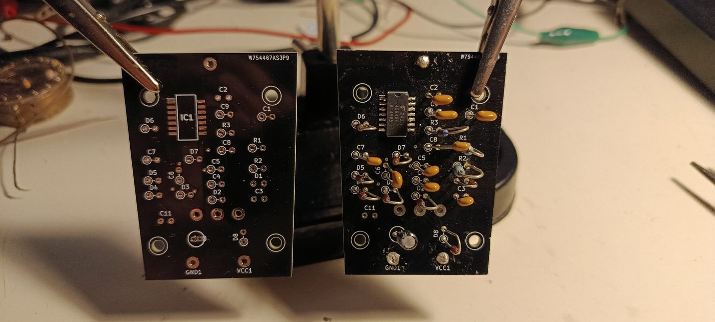
The first board amplifies. It takes the tiny signal from the membrane and makes it strong enough to travel down a cable to a computer without losing quality. This is the delicate part of the project: the signal is so faint that the components can let almost no current through — hence resistors of a billion ohms, an unusual value even in electronics.
The second board makes a high voltage. The membrane has to be charged, and this board produces that charge from the power the audio interface supplies, raising the voltage one step at a time.
Why two boards instead of one?
- The second board makes a very fast buzz — 76,000 oscillations a second. You can't hear it, but it's there. Keeping it physically away from the fragile circuit stops it getting into the sound.
- If one board fails, or you want to swap one, you only replace that one.
05 How it's all drawn
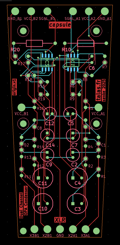
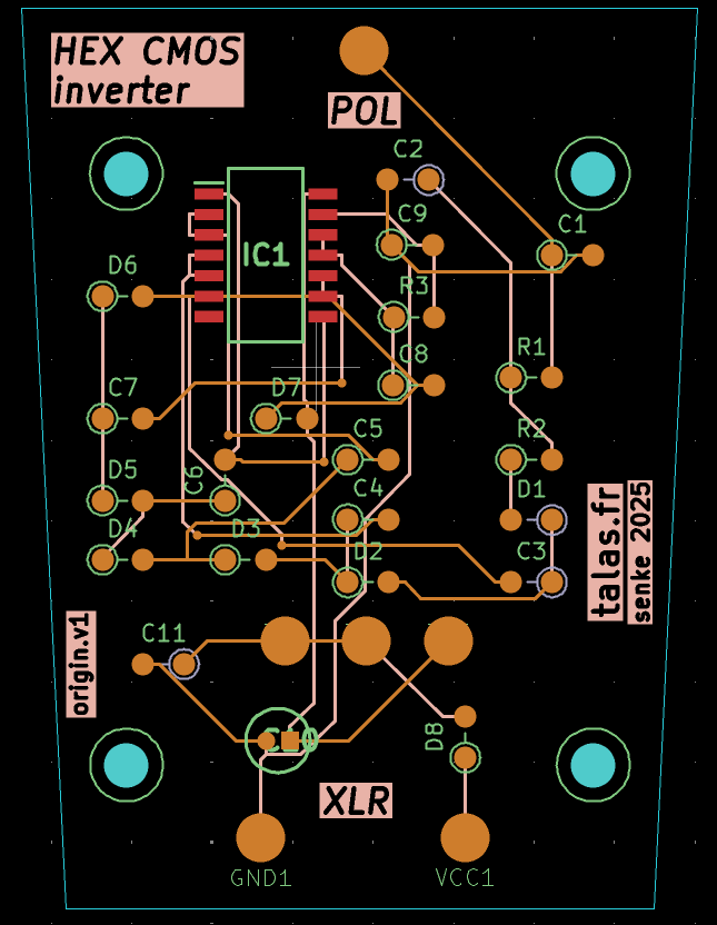
Nothing here is left to chance. Before a single board is ordered, everything is drawn in design software, in two stages:
- The schematic — which part connects to which. It's the logical plan, like the wiring diagram of a house: you know the switch works the lamp before you know where the cable runs.
- The layout — where each part sits on the board, and the path each copper track takes. That's the architect's plan.
The two screenshots above show the second stage: each coloured line is a copper track, each round spot a pad where a component will be soldered.
The software then runs through a long list of checks on its own: two tracks touching, a track too thin for the current it carries, a forgotten component. Only when they all pass do the files go to the manufacturer, who sends the bare boards back a week or two later.
06 Assembly
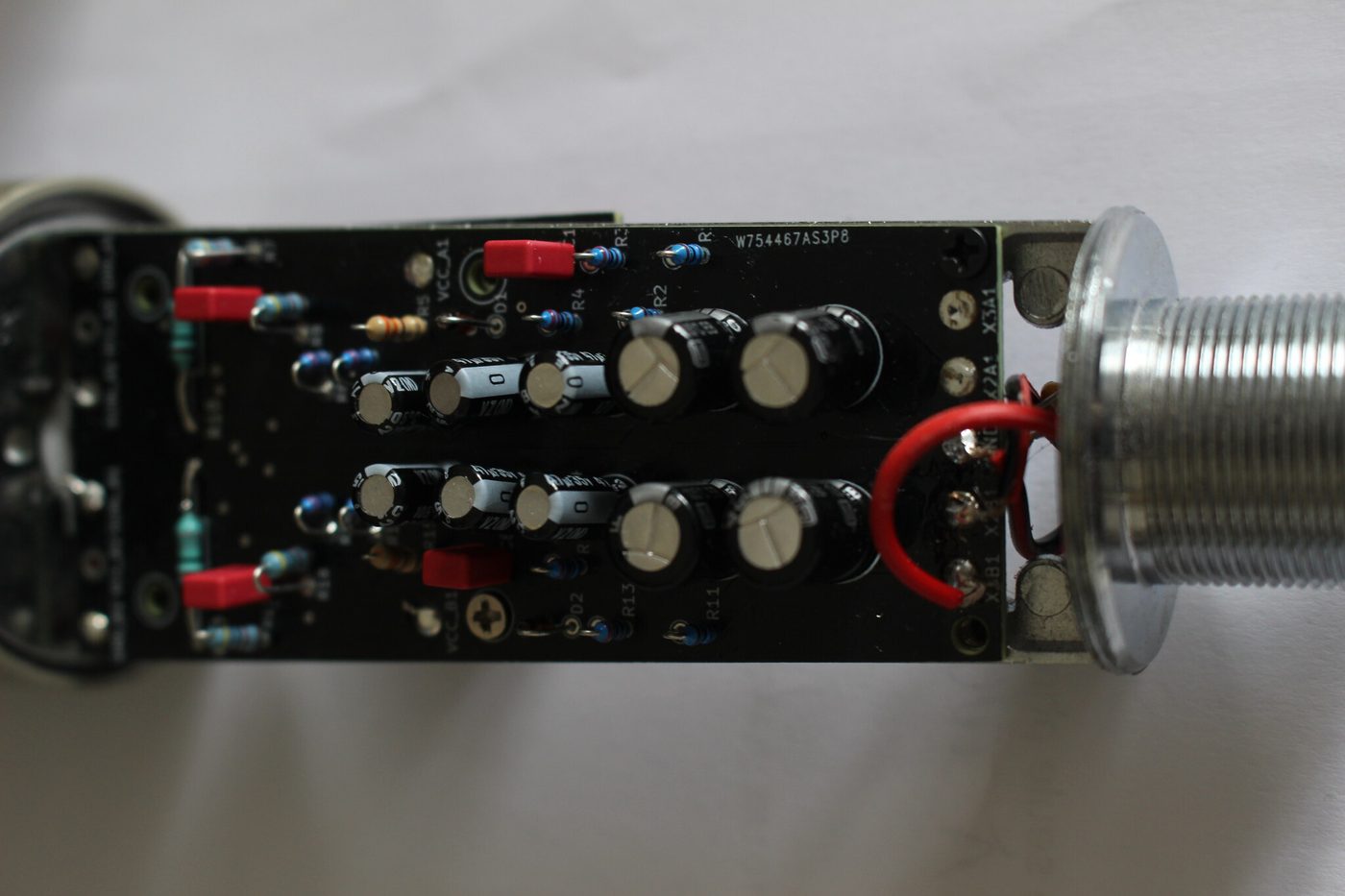
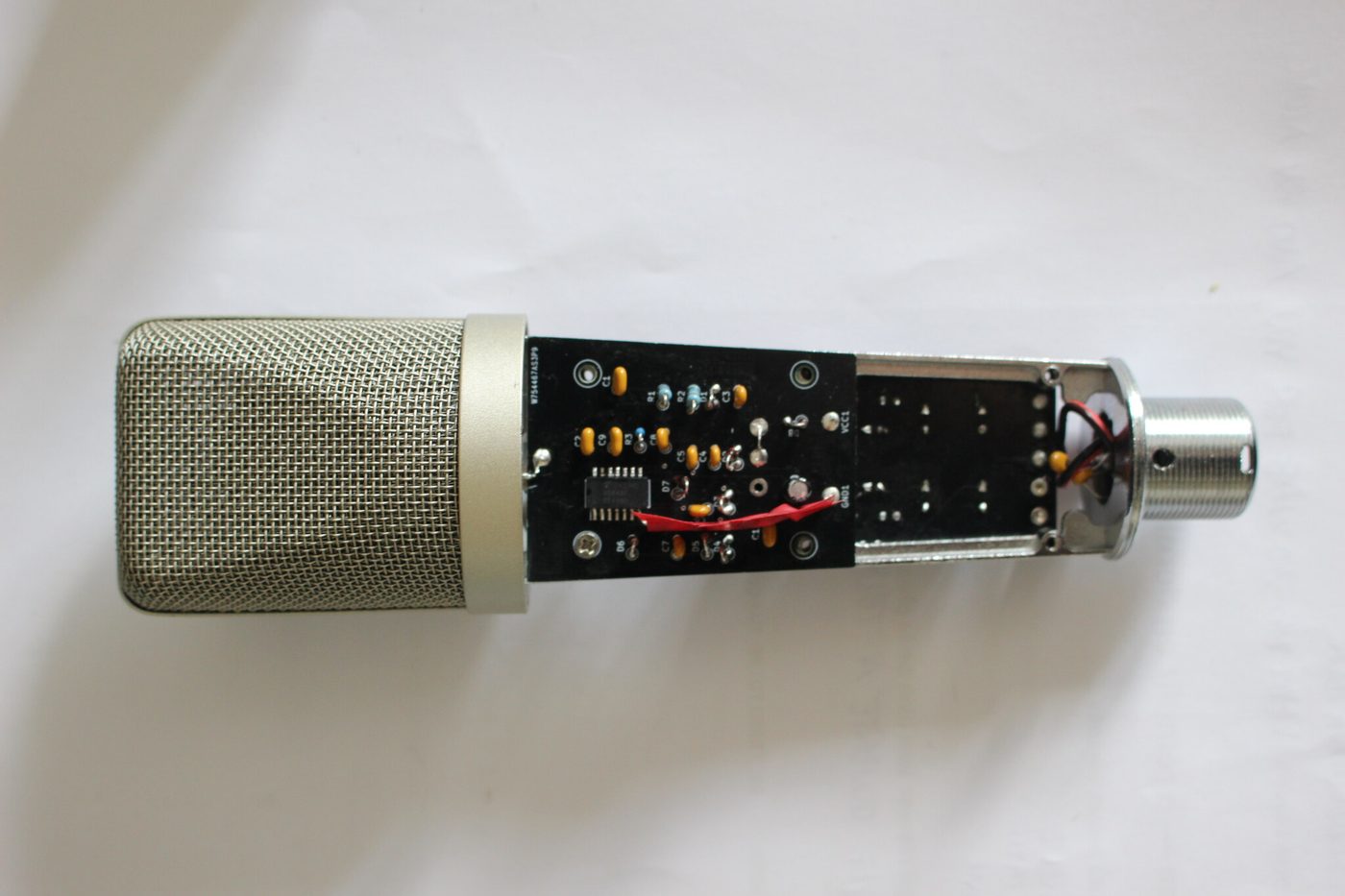
The boards arrive bare. Every component then has to be soldered on by hand — some are smaller than two millimetres — before the two boards are wired to each other, to the capsule, and to the socket at the back of the mic.
Allow four to six hours for a complete build, and a good magnifier.
To help you find your way, the repository has an interactive bill of materials: preamp · hex. The parts list is on one side and the board on the other: click a part and it shows you where it goes. It's what makes the build doable without printing anything.
07 The test bench

This is what the work really looks like: boards lying flat, crocodile clips, an oscilloscope probe, a soldering iron, and the capsule sitting in the middle of it all.
The photo is here on purpose. An electronics project isn't a tidy model on a white background. It's two days of debugging to work out why a channel stays silent, a part burnt out along the way, and wires added by hand to make up for a layout mistake.
08 Does it actually work?
Yes, on one of its two channels. The first recording dates from 12 April 2026, after two days of debugging. The other channel has never made a sound: one of its parts was destroyed during debugging. The design fault behind it is fixed in the current revision of the boards (P3) — but only a P3 board can prove it, and none has been made yet.
"It works" isn't enough, though: you need to know how well. So the mic was set up next to a very common studio mic, the Rode NT1-A (about €200), with both listening to the same source at the same moment. Comparing the two cancels out the room and the loudspeaker, leaving just the difference between the mics.
- ✓Its output level is on a par. In the calibrated June 2026 measurement, its sensitivity came within 0.1 dB of the NT1-A — a negligible gap.
- ✓It sounds different. Warmer and fuller in the low mids, softer in the highs. The NT1-A is bright, a little cutting; this one is the opposite. On a sibilant voice, it's more forgiving.
- ✓It's clean. No stray resonance, no smearing: when a sound stops, the mic stops with it. No clipping up to −1 dBFS.
- !It still picks up some mains hum. Its background noise sits in the bass, on the lines of household mains power (50, 100, 150 Hz). Its absolute noise level hasn't been measured reliably yet.
- !It distorts slightly in the mids. Around 500 Hz, 1–2 % distortion, more than the reference mic. We haven't found the cause yet.
The two weak spots, explained
They're listed because they're real and we know what they are — and because a project that only showed its successes wouldn't deserve to be believed about the rest.
- The hum comes from grounding: how well the electronics are bonded to the metal body. A solid bond cuts the hum, and it also steadies the voltage that charges the membrane.
- The distortion. At first the bass looked badly distorted (several percent at 50 Hz). Most of that turned out to be mains hum caught by the measurement; leave the hum out and it drops to about 0.24 %. What's left is a smaller residual in the mids, around 500 Hz, still to be tracked down.
A word on honesty. These measurements come from a single unit (the P1), repaired by hand, measured in an ordinary room with a consumer loudspeaker — not in a lab. The shape of the results is reliable and holds from one method to the next; the exact values aren't.
09 Hear the difference
So far you've been looking. This is the part that matters most: what it sounds like.
Both excerpts date from June 2026, so they're the mic as it is today: inside its metal body, with the voltage that charges the membrane stabilised. Each time, the Talas and a Rode NT1-A — a shop-bought studio mic — heard the same source at the same moment, on two inputs of the same audio interface.
Music
The most revealing test: real music, played in the room, picked up by both mics at once.
What to listen for: the NT1-A is crisper at the top, with cymbals and consonants pushed forward — more "present", sometimes harsher. The Talas is rounder and calmer, with fuller low mids. Two different characters; neither is better outright.
Pink noise
Pink noise contains every frequency in equal measure. That makes it the most telling signal for comparing two mics: any difference you hear has to come from the mic, not the source.
What to listen for: the NT1-A hisses more in the treble — brighter, a little more aggressive. The Talas is duller, rounder, more muted. That's the "warm" signature from the graphs, except this time you can hear it.
How these excerpts were made. Each pair comes from a single two-channel recording, cut at the same point. For the pink noise, the same gain was applied to both (+10 dB), and the measured levels are within 0.3 dB of each other. For the music, the input gains weren't matched while recording, so the levels were evened out afterwards, to within 0.7 dB. Either way, the difference you hear is the mics, not a setting. It's clearer on headphones. These excerpts are for listening; the 0.1 dB sensitivity figure above comes from the separate, calibrated measurement.
Still missing: a voice recording. It's the first thing you'd want to hear from a studio mic, and there isn't one of the mic as it is now. The only voice recordings date from April, before it went into the metal body, and they suffer from the mains hum the body got rid of. Publishing them would give the wrong picture.
10 The measurements, as pictures
Show the nine graphs — optional, and the most technical part
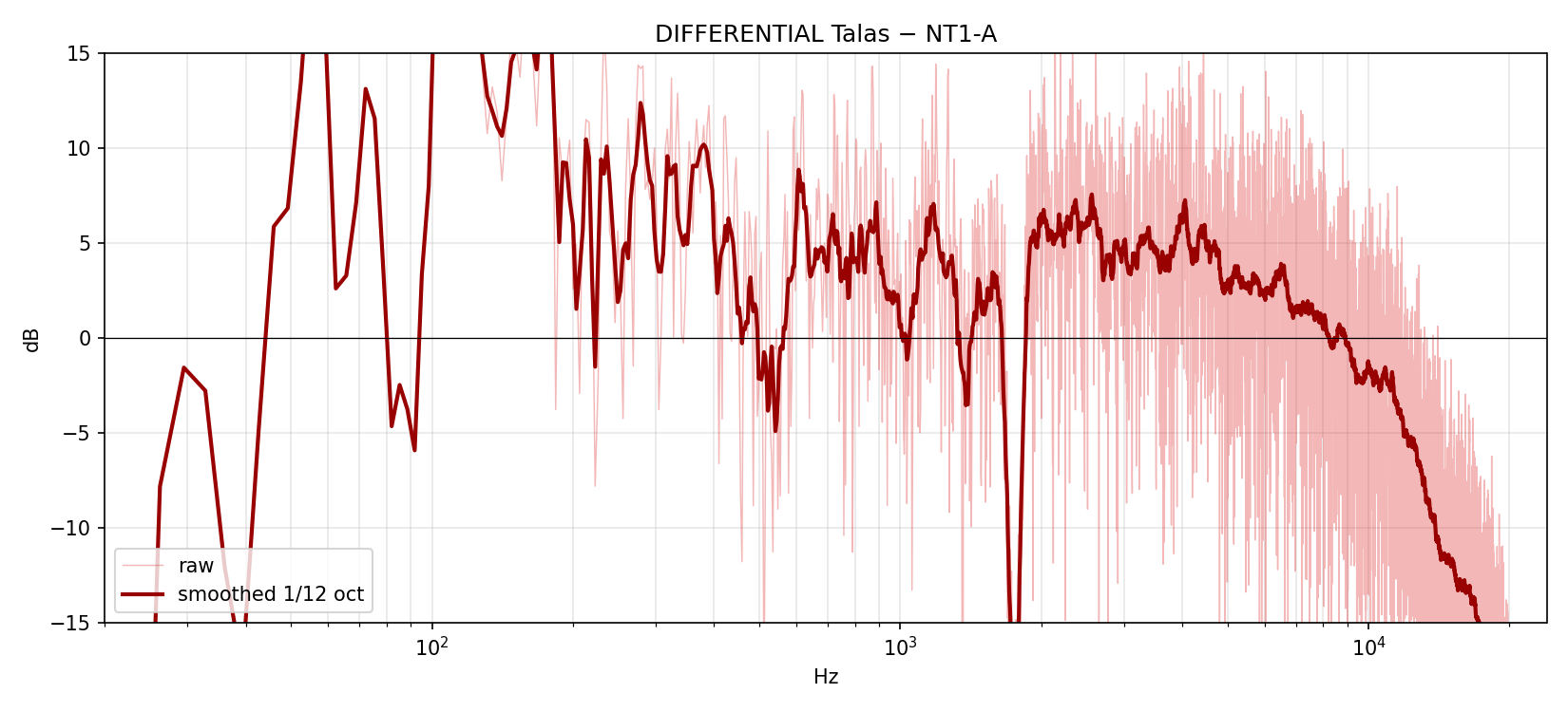
How to read these curves, in two sentences. Left to right runs from low sounds to mids to highs. Where a curve rises, that range comes through more; where it dips, it's held back.
The sound signature
Timing

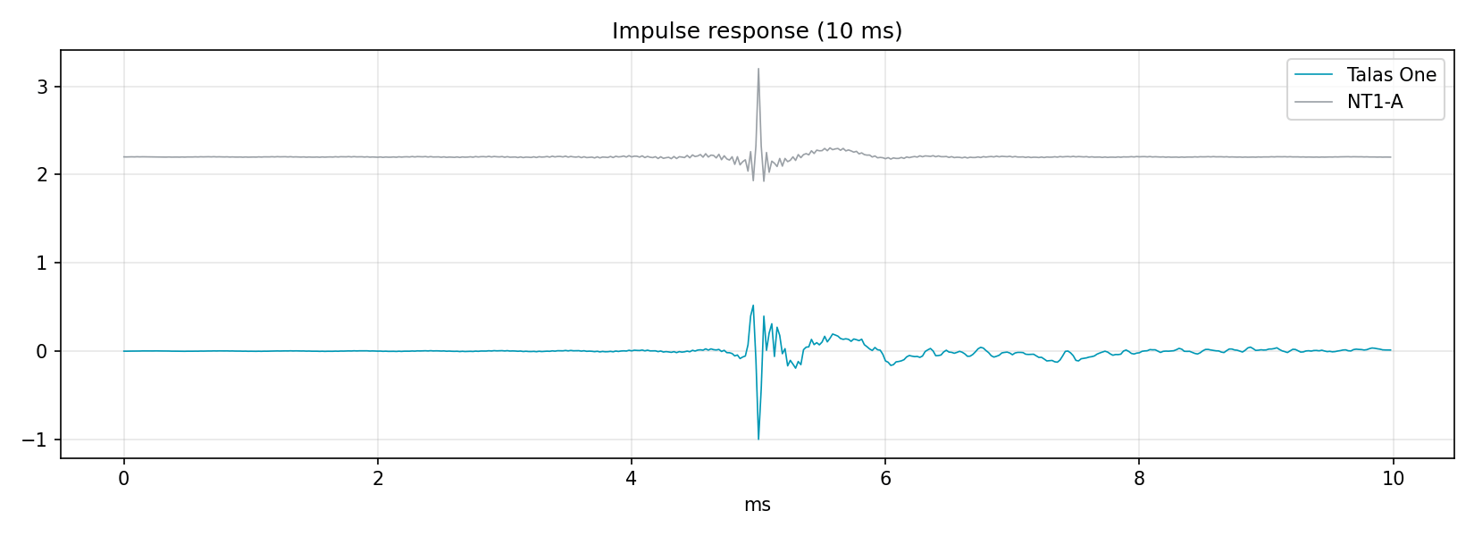
These two check that the mic doesn't shift sounds in time or ring on after a sharp click. Both look good.

Distortion
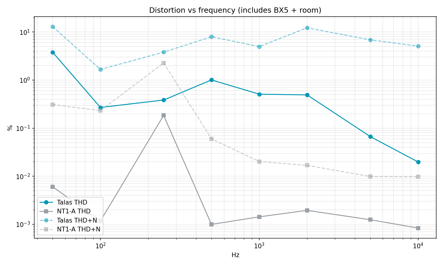
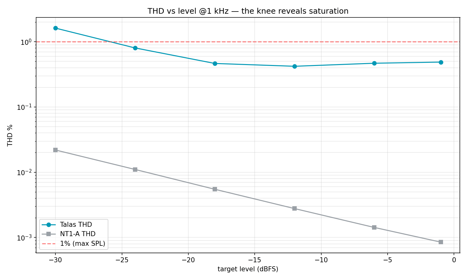
Distortion is whatever the mic adds to the original sound. On the left, the rise at the low end is mostly mains hum caught by the measurement (see stop 8); the real residual sits around 500 Hz. On the right, we check that the mic doesn't saturate as the volume goes up — and it holds.
Noise and dynamics
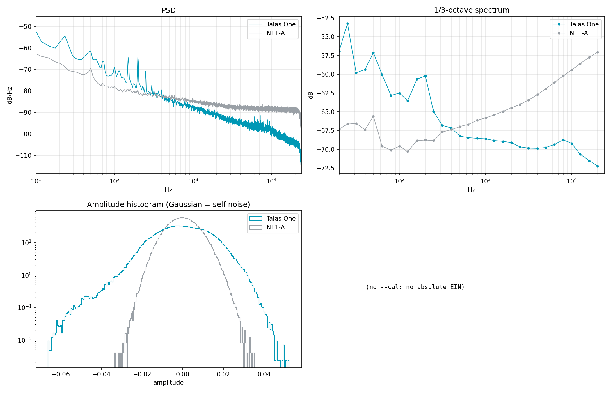
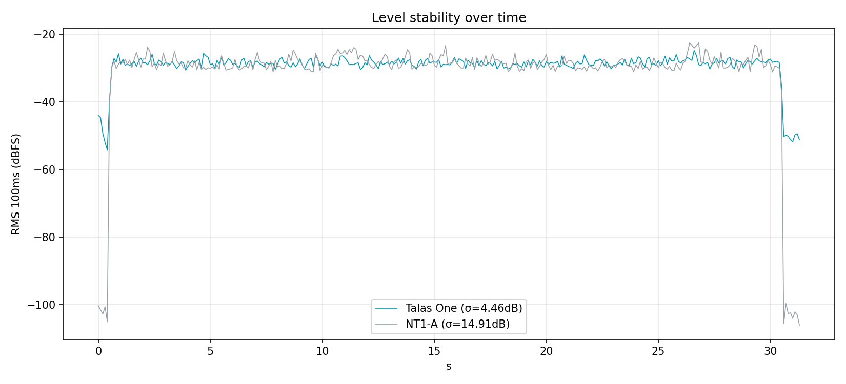
On the left, where the noise comes from: the lines of household mains power (50, 100, 150 Hz) and a noise that sits in the bass, while the NT1-A hisses more in the highs. On the right: the mic doesn't squash the gap between loud and quiet sounds.
All on one page

Raw data: the test recordings behind these graphs are published in the companion repository mic-test-bench, along with the measurement tools.
11 How the project got here
A year of work, from the first sketch to today.
- 21 March 2026First sources published: the project goes public.
- 1 April 2026First complete release — schematics, manufacturing files, parts list, photos and build guide.
- 12 April 2026First successful recording, after two days of debugging. Only one of the two channels works; the other was damaged during testing. First comparison with an entry-level mic the same day.
- 29 April 2026The prototype is documented inside and out — failures included — and a second version of the boards is drawn.
- 11 May 2026Second version of the power-supply board drawn. The mic goes into its metal body, and the 50 Hz hum disappears.
- 31 May 2026Reference recording session: background noise, frequency sweeps, channel matching.
- 3–4 June 2026Measurement campaign against the Rode NT1-A. The big finding: the voltage charging the membrane was unstable, which had skewed every earlier measurement. Once it was stabilised, the mic's sensitivity came within 0.1 dB of the NT1-A.
- 28 June 2026Third version of the boards (P3): layout reworked to get rid of the hand-added wires.
- August 2026The documentation is checked line by line against the board files, and the check becomes automatic.
- 2 September 2026P3 manufacturing files published: two-layer boards, every automated check passing.
- 29 September 2026Latest P3 files: ENIG finish, silkscreen labels back on the preamp board, every part checked against its datasheet. Still not manufactured.
The second version of the boards was drawn but never made; its fixes went into the third.
12 Why everything is public
The plans, the measurements, the parts list and the mistakes are all published under an open licence. Anyone can build this mic, modify it, or build on it — even to sell it — as long as they publish their own changes in return.
That includes the failures: a diode burnt out while debugging, two layout errors on the first version, a hum that only went away once the electronics were in metal, and an unstable voltage that skewed weeks of measurements.
That's unusual. Most projects only show what worked. Here, anyone rebuilding the mic knows in advance where they'll hit trouble — and that's exactly what makes the project useful to others.
13 Where it stands, and what's next
- Done
- one prototype (P1) that records, measured
- Designed, not yet made
- version 3 of the boards (P3)
- Next
- manufacture and measure the P3
Version 3 of both boards builds the hand-added wires into the design, and passes every automated check. No P3 board has been made yet.
What's left, in order:
- Manufacture and measure the P3 — both boards, both channels.
- Measure several capsules — to find out how much one differs from the next, and publish the raw data.
- Reference measurements under controlled conditions — frequency response, noise, distortion, maximum level, polar pattern.
- Improve the measurement tools so anyone can use them with a cheap audio interface.
- Finish the hardware release — open-hardware certification (OSHWA), a parts list sourced in Europe with alternatives, and frozen manufacturing files.
- Rebuild from the documentation alone — two complete units built only from the published files, then measured.
- Validation by others — one or two volunteers build it from the documentation, and every point where they get stuck is written down and fixed.
The project is self-funded, as everything so far has been. An application to the NGI Zero Commons Fund (NLnet Foundation) wasn't selected in September 2026 — 44 out of about 1,000 applications were funded that round. The list above is still the work that funding would pay for.
An idea for later, beyond this list: a mic whose pickup pattern you could change with a knob — hearing only what's in front of it, or all around.
For now, this is a research project run by one person. Nothing is for sale.
14 Frequently asked questions
- "Why not just buy a mic?"
- Because the point isn't to own a mic — it's to understand how one works, and to be able to change it. A shop-bought mic is a closed box: if it doesn't sound the way you want, there's nothing you can do.
- "Does it sound better than a shop-bought mic?"
- No — and that's not the goal. It sounds different: warmer, softer. On some voices that's better, on others it isn't. It also still picks up some mains hum, which comes from grounding and is being worked on.
- "How long did it take?"
- About a year from the first schematic to today, worked on in bursts.
- "Can I buy one?"
- Not today: there's no production run and nothing is for sale. talas.fr has a waiting list — no commitment, no payment. In the meantime, everything is published so you can build your own: allow about €78 of parts plus an adapter cable, and a day's work if you already know how to solder.
- "What's the hardest part?"
- Handling such a weak signal without messing it up. Everything else — soldering, ordering the boards, putting it together — is within reach of anyone patient.
15 Going further
| If you're wondering… | Look here |
|---|---|
| Where does the project stand? | STATUS.md — the current state, on one page |
| What does it really cost? | bom/ — the parts list, to the cent |
| Could I build one? | assembly-guide.md — the build guide |
| Where does each part go? | interactive bill of materials — preamp · hex |
| How do you know it's any good? | measurements.md — the measurement campaign |
| What went wrong? | known-limitations.md, bodges.md |
| Why these choices? | design-philosophy.md |
| What does it sound like? | audio-samples.md — what exists and what doesn't |
| And the full technical picture? | README.md |
And the workshop behind it
The Talas One is the first thing a workshop makes, not the start of a product line. The workshop has one rule everywhere: publish the plans, publish the costs, and build nothing people can't take back control of.
Applied to a service instead of an object, that rule gives you Veza — a platform where musicians share their tracks, work on them together and sell what they make. Self-hosted, no data resale, and the commission shown up front.
talas.fr — the mic and the workshop · veza.fr — the platform
Quick glossary
| Term | What it means |
|---|---|
| Capsule | The part that hears: a thin membrane that vibrates with the air. |
| Preamp | The circuit that turns a too-weak signal into a usable one. |
| Board / PCB | The small plate the components are soldered onto. |
| Schematic | The plan of what connects to what. |
| Layout / routing | The plan of where the parts and tracks physically sit. |
| P1, P3 | The prototype that exists (P1), and the current, improved board revision that hasn't been made yet (P3). |
| Open hardware | The plans for a physical object, published freely — like a recipe. |
| dB (decibel) | A unit of comparison. +6 dB is "clearly louder"; −12 dB is "clearly quieter". |
| Faraday cage | A metal enclosure that shields against electrical interference. |
| Distortion | Whatever a device adds to the original sound. The less, the more faithful. |
| Phantom power | The power the audio interface sends up the cable to run the mic. |